
// YOU MIGHT ALSO LIKE
Tray Channel 40x25
ID + IC Braclet Tag
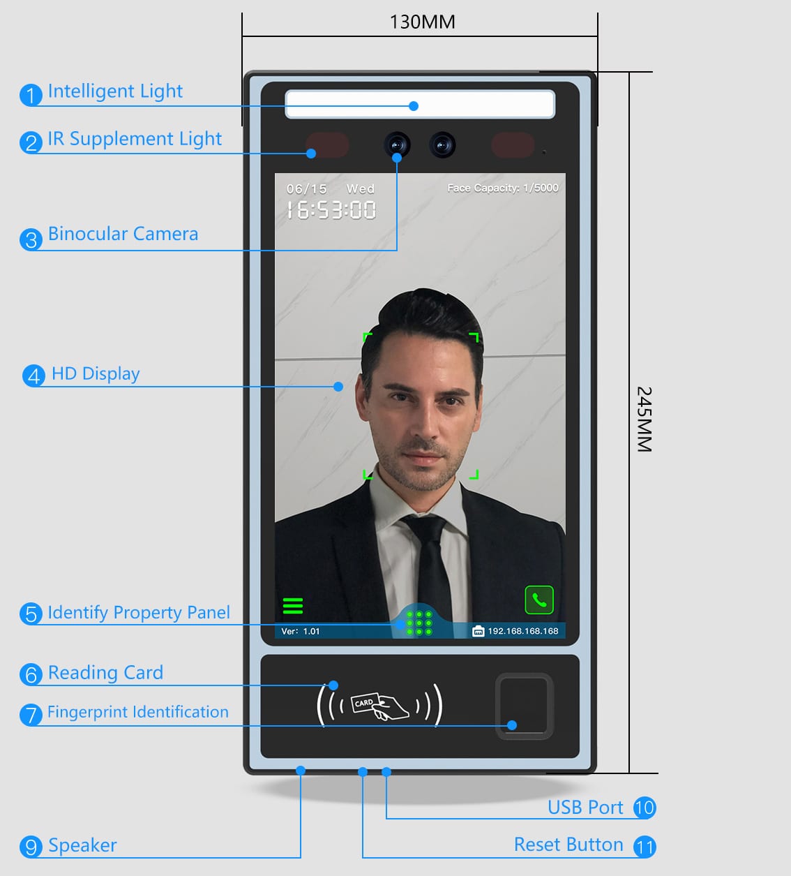
FC-8890H 8-inch fingerprint face machine, waterproof
Main Uses: Access Control, Time Attendance, Video Intercom, Elevator Control, Cabinet Lock Working Voltage: DC12V(9 ~ 14V) Working Current: <2000mA Working Environment: Temperature: -30℃~65℃; Humidity: 10 ~ 90%, RH Operating System: LINUX System User Capacity: 20,000 Faces; 20,000 QR Codes; 20,000 Cards; 20,000 Passwords; 10,000 Fingerprints; Record Capacity: 1 Million Records; 10,000 Recording Photos; 10,000 System Records Recognition Distance: 0.3m-3m Recognition Speed: < 0.3S Material: ABS Plastic Casing+Tempered Glass Panel Size: 215×112×25mm Weight: 0.6KG Elevator Expansion: Support for Elevator and Cabinet Lock Algorithm: Face Recognition, Fingerprint Identification, Palm Vein Recognition, QR Code Verification Management Mode: Touch Screen, Desktop Software, Cloud Software, Mobile App Registration Methods: Face, Fingerprint, Palm Vein, Password, Mifare Card, Dual Frequency Card Optional (ID Card and Mifare Card) Comparison Mode: 1:N/1:1 Firmware Upgrade: Software OTA Upgrade or USB Flash Drive Upgrade Camera: Wide Dynamic Binocular 2 Megapixel HD Camera Display Screen: 8-inch ISP Full-view HD Screen Storage: 256M DDR3 Memory, 8GB EMMC Storage Communication: TCP/IP, WIFI, 4G(Customized), Wiegand26/34/66 Other Interfaces: Exit Button x1, Door Sensor x1, Fire Input x1, Alarm Output x1, Wiegand Output x1, Wiegand Input x1, Magnetic Lock Control x1, USB x1, RS485 x1 Installation Ways: Wall Mounted or Installed on the Turnstile
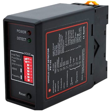
PD-132 Single Vehicle Loop Detector
■ Install Detector The detector must be installed in a convenient weatherproof location as close to the loop as possible. Installation location must choose to stay away from the heat source, it around other devices must maintain a distance of at least 10mm (mustn’t fix cling to the cabinet). A correct loop configuration and detector installation will ensure a successful inductive loop detection system. Loop of several important parameters include: loop figure, size, and turns, install methods (details as “Loop installation guide”). ■ Wiring Diagram PCD-132 Diagram.jpg ■ Operation and Indication While the detector is tuning, the green Channel LED and red Power LED will be turn on. It remain about 2 seconds, then the green LED turn off. If a loop fault exists the Channel LED will come on and flash indicating a fault. If the fault is self-healing the detector will continue to operate. The green channel LED will also glow whenever a vehicle is detected passing over the inductive loop. The red Power LED at the top of the unit will remain on to indicate that the unit is powered. ■ Frequency To eliminate interference of two neighbouring wire loops or loop detectors, the frequency can be altered. PD132 Frequency.jpg ■ Sensitivity The sensitivity of the detector allows the detector to be selective as to the change of inductance necessary to produce an output. There are four sensitivity selections and are set as follows by DIP3 and DIP4 Switch. PD132 Sensitivity.jpg ■ Automatic Sensitivity Boost Automatic sensitivity boost is selected by DIP5 switch on the front of the enclosure and is set as follows: OFF - Disabled, ON – Enabled. Automatic sensitivity boost causes the sensitivity to be boosted to a maximum on detection on the vehicle, and maintained at this level during the presence of the vehicle over the loop. When the vehicle departs the loop and detection is lost the sensitivity reverts to the pre-selected level. ■ Filter To eliminate interference of bad environment, the filter mode is activated by setting the DIP6 Switch to “ON” site. In filter mode, the reaction time of the detector is delayed, and the sensitivity is reduced. Usually, the filter mode is disabled by setting the DIP6 Switch to “OFF” site. 【Attention】 If the detector isn’t working normally, you must check the loop and wiring at first, and then alter the frequency or the sensitivity. At last ,try to set it to filter mode. ■ Output Relay The relay2 is pulse output. If DIP7 is “OFF” site, when a vehicle is detected passing over the inductive loop, the relay is energized( Pin3 and Pin4 is shorted) and de-energized ( Pin3 and Pin4 is opened) after 500ms. If DIP7 is “ON” site, when a vehicle is detected departing the loop, the relay is energized ( Pin3 and Pin4 is shorted) and de-energized ( Pin3 and Pin4 is opened) after 500ms. The relay1 is presence output. When a vehicle is detected passing over the inductive loop, the relay is energized( Pin5 and Pin6 are shorted) until the vehicle is detected departing the loop. ■ Presence Time The presence time may be set to permanent presence or to limited presence. In permanent presence mode the detector will continuously compensate for all environmental changes whilst there is a vehicle present over the loop, the presence mode is set with DIP8 Switch and is configured as follows: OFF:Limited Presence ( 5 minutes), ON:Permanent Presence. ■ Reset Switch The detector automatically tunes to the inductive loop connected to it when the power is applied, whether on initial installation or after any break in power supply. Should it be necessary to retune the detector, as may be required after changing any of the switches or after moving the detector from one installation to another, momentary operation of the RESET switch will initiate the automatic tuning cycle. ■ Technical Data Product Parameter Parameter Descr1ption S4A Model PD-132 Product Name Single Vehicle Loop Detector Supply voltage 230V AC , 115V AC, 12/24V DC/AC ( See the label on the detector) Voltage tolerance AC +10% / -15%; Voltage tolerance DC ±15% Power Consumption 4.5VA Output relays 120V/3A AC Operating temperature -20°C to +65°C Storage temperature -40°C to +85°C Frequency range 20 kHz to 170 kHz Reaction time 10ms Signal holding time Unlimited / limited when loop is permanently covered 5 minutes Sensitivity Adjustable in 4 increments Loop inductance Total loop plus connection wiring 50 to 1000μH.Ideal is 100 to 300μH Loop connection wiring Maximum length 20 meters, twisted at least 20 times per meter Size of Housing 78x40x108 mm (L x W x H)